


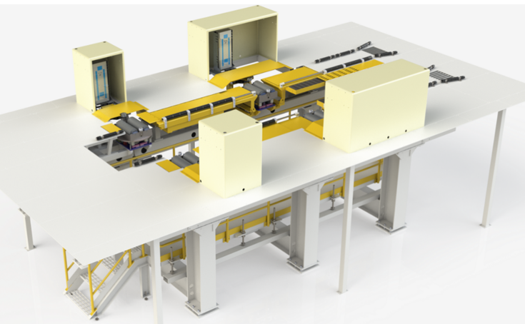
Non-contact four-wheel locator ——WAT-2000
 W heel A lignment S ystem—WAT-2000
Place of origin: China
Manufacturing company: IYASAKA
Testing concepts
A platform used to measure and evaluate parameters and components such as vehicle camber, caster, kingpin camber, kingpin caster, thrust angle, steering angle, etc.
Meet the requirements of online adjustment of front beam and external inclination.
Test principles
The four-wheel positioning sensor utilizes IYASAKA independently developed 3D laser sensing technology. By employing dynamic laser illumination matrix reconstruction, it generates tire surface 3D images at 10/20 Hz frequency. This enables accurate determination of front camber and caster angles through tire 3D modeling. The system can be configured with wheel bead height measurement units for vehicle body (wheel bead) height assessment. It also supports expandable functions including axle load measurement and steering angle monitoring.
test item
toe-in
- extraversion
- Main pin backward tilt/Main pin inward tilt (optional)
- Rim and eyebrow height measurement system (optional)
- Shaft weight measurement system (optional)
- Rudder Angle measurement function (optional)
Test model
- Passenger cars and commercial vehicles
Product features
More test functionality and higher test quality
- High measurement accuracy, small repeatability error and stable operation
- The new floating mode of the drum unit has the characteristics of small friction, smooth sliding and sensitivity, which can help improve the repeatability of test data. At the same time, it also has the function of aligning the vehicle when detecting and adjusting the vehicles front lamp
- Iyasaka and Visicon are two laser options that adapt to a wide range of prices
- The modular design is simple to arrange, easy to maintain, high cost performance, low maintenance cost and use cost
- Image processing patent technology
- Servo technology is used for centering and central torque feedback
- The floating platform uses air suspension technology to minimize mechanical resistance and has higher accuracy
scope of supply
The four-wheel positioning equipment of WAT-2000 includes:
There are two sets of mainframe and vehicle driving channel, one set on each side (installed in the pit)
- There are two sets of shaft adjustment devices, one for each left and right channel (installed in the pit)
- There are 4 sets of floating plates driven by motor, one set for each wheel
- There are 4 sets of vehicle center positioning device, one set for each wheel
- One set of lighting device for the pit
- One set of operating platform in the pit (adjustable height)
- A set of cover plate, ladder, handrail and fence
- 3D laser sensor (Iyasaka/Visicon) 4 sets, one set per round (Visicon is more expensive)
- Electrical control cabinet (including mainstream PLC and PC) 1 set (including circuit, button indicator light, UPS, display, servo control, etc.)
- A set of steering wheel Angle tester and accessories (including instrument body/handheld home/charging base/calibrator)
- Drivers assistant display 3 sets (2 sets in the pit, 1 set on the ground)
- Drivers operation button box 1 set (model selection, start, end, reinspection, emergency stop, etc.)
- Barcode scanner or RFID reader (option)
- Static calibration frame
- Dynamic car (optional)
- Four-wheel positioning inspection software IAMachVision For WAT (for OEM online inspection)
- Complete technical data, including Chinese and English version of data book (including electrical circuit diagram, operation manual, installation manual, etc.).
essential parameter
| Allowable axle load (parameters can be customized according to requirements) | 2 000kg/axle | |
| Allowable wheelbase (parameters can be customized according to requirements) | 1940-2840/2300-3200/2600-3800, etc | |
| Test speed (dynamic test) | About 4km/h | |
| Roller dimensions | ||
| Front roller (parameters are customized according to requirements) | Internal width x external width ( between centers ) | 1250×2150mm 1700mm |
| Outside diameter x length | Ø186×450mmmm | |
| Back roller (parameters are customized according to requirements) | Internal width x external width ( between centers ) | 1250×2150mm 1700mm |
| External diameter × face length | Ø186×450mmmm | |
| Shaft spacing | 220mm | |
| Rolling drum motor (passenger car) | 0.75kW, 4P,4 units | |
| Roller braking | Pneumatic mechanical brake, can be maintained | |
| Rolling floating platform | New type of ball floating | |
| Axis setting method | The rear roller section is mobile | |
| Shaft offset moving motor | Servo motor, 0.75kW, 2 units | |
| translational speed | Greater than 60mm/sec | |
| Mobile precision | ±1mm | |
| way | Automatic movement, acceleration and deceleration servo control | |
| To the middle roller | ||
| 1) Static test mode | The vehicle is aligned | |
| 2) Dynamic test mode | Vehicle center and test deviation | |
Range and precision
| project | measurement range | accuracy | repeatability precision | remarks |
| toein | ±8° | ±1ˊ | ±0.2ˊ | Must be checked |
| camber | ±5° | ±2ˊ | ±0.4ˊ | Must be checked |
| Main pin backward tilt (measuring the inner and rear tilt angles of the main pin by an external sensor) | ±15° | ±0.2° | - | Sampling items |
| Main pin inclination (measuring the main pin inclination and backward inclination Angle by external sensor) | ±12° | ±4° | - | Sampling items |
| Steering wheel inclinometer | ±1 5° | ±0.1° | ||
| Improve the angular measurement accuracy | ±2ˊ | |||
| steering locking angle | ±45° | ±1° | - | Sampling items |
| wheel load | ≥1000kg | ±2% | - | option |
Check the beat
| order | Check the procedure | Inspection methods | time |
| 1 | The shaft is moved to the right position, the green indicator light of the display is on and the red indicator light is off, and the vehicle can enter the detection | Visual, operational | |
| 2 | The vehicle enters the equipment, the model is read, and it is confirmed that the front axle of the vehicle is in place and the N gear is engaged | operate | 4 |
| 3 | Start the S/W, the red indicator light of the display is on and the green indicator light is off. Other vehicles are prohibited from entering | operate | 3 |
| 4 | Install the head level | operate | 5 |
| 5 | Start four-wheel positioning test | operate | 1 |
| 6 | Lift up and block the drum from rising | Equipment action | 2 |
| 7 | Roller starts, vehicle centering, measurement is completed, display measurement data | Equipment action | 15 |
| 8 | Move the light instrument to the detection position and turn on the low beam | Equipment action | |
| 9 | Adjust front axle camber | check | 35 |
| 10 | Adjust front axle toe | check | |
| 11 | Left low beam adjustment (optional) | check | |
| 12 | Right low beam adjustment (optional) | check | |
| 13 | Switch high beam (optional) | check | |
| 14 | Left and right high beam measurement (optional) | check | |
| 15 | The front beam and the light are adjusted. Remove the steering wheel level and put it back to its original position | operate | 3 |
| 16 | At the end of the test, the display shows the test results and confirms the four-wheel positioning data | visual | 2 |
| 17 | Lift to block the roller from returning to its original position | Equipment action | 2 |
| 18 | After the detection is completed, according to the display prompt, confirm the safety, and then drive out. The red light is off and the green light is on | Visual, operational | 4 |
| amount to | 76 |
Non-contact four-wheel locator——WAT-2000
Contact Us
Keywords


Telephone:
E-mail:
ZhenHua Packing Machinery
Online Message
WebsiteConstruction: China Cross-border Enterprise | SEO
在线客服添加返回顶部
右侧在线客服样式 1,2,3 1
图片alt标题设置: Iyasaka (Beijing) Automotive Technology Co., Ltd.
表单验证提示文本: Content cannot be empty!
循环体没有内容时: Sorry, no matching items were found.
CSS / JS 文件放置地