


Advanced Driver Assistance Calibration System——ADAS-2000
Place of Origin: China
Manufacturing Company: IYASAKA Beijing
Equipment Name and Model
The ADAS-2000 Advanced Driver Assistance Calibration System includes:
- Aluminum alloy gantry
- Vehicle alignment
- Passive ACC light box (including CCD camera and Fresnel lens)
- Active ACC metal target
- LDW black and white pattern target for front/back camera
- Front/back angle radar BSD triangle target
- Rim and eyebrow height measurement system (optional)
- Laser emission standard target (optional)
- Electrical control cabinet (including PLC, servo driver, industrial computer, etc.)
- Adas calibration software IA-ADAS (for online adjustment in the car factory)
- Driver assists display
- Calibration stand (for calibration)
- Complete technical data, including Chinese and English version of data book (including electrical circuit diagram, operation manual, installation manual, etc.).
Detection Principle
The system employs dual pneumatic control alignment mechanisms at both ends, enabling the alignment lever to drive wheels symmetrically along the equipments geometric centerline. This ensures both front and rear wheels align precisely with the equipments central axis. The alignment device maintains vehicle levelness with ≤±1mm tolerance across any XY plane point. Servo motors drive multiple functional targets to designated positions, while IYASAKA proprietary ADAS calibration software communicates with the vehicles ECU. This enables precise adjustment of sensor installations (including cameras, radar, LiDAR, etc.) in terms of positioning, orientation, coordinate systems, and alignment with other vehicle systems. The system guarantees that sensor data matches real-world physical space, ensuring accuracy and reliability for ADAS features like lane-keeping, adaptive cruise control, and automatic emergency braking.
Measurement Items
- ACC/FCW front collision warning;
- LDW lane offset calibration;
- BSD blind zone monitoring and calibration;
- Measuring the height of the rim;
- SVM/360 Panorama impact calibration;
- HUD calibration (optional);
- Laser emission calibration (optional)
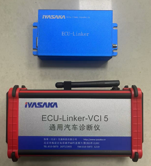
General‑Purpose Vehicle Communication Interface——VCI5
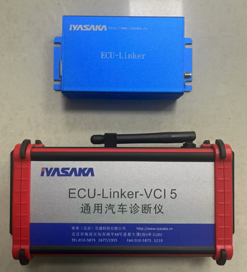
- Supports 4 CANFD/CANBUS bus data transmission;
- Connect the cars BD cable to power the diagnostic instrument;
- Supports Bluetooth wireless and 232 serial port cable transmission;
- Support multiple automotive bus protocols
- Support the secondary development interface function of the host computer.
- Integrated with 4 CANFD/CANBUS communication modes;
- Supports 1 K bus communication mode;
- Integrated with 1 DOIP bus communication mode;
- Wireless and wired automatic switching;
- The signal light indicates the working status
Basic Parameters
| Main technical parameters of automotive suspension device | |
| Allow maximum load capacity | 3t |
| Allow the wheelbase of the car | 2200-3200㎜ |
| Allow wheelbase | 1400-1600mm |
| Front panel width | 1000㎜ |
| Width of rear panel | 1200㎜ |
| Thickness of mobile panel cover | 8mm |
| accuracy of alignment | Left and right: ±2mm; front and back: ±5mm |
| Time to respond | <2s (adjustable) |
| Frame splicing mode | Rectangular tube welding, bolted connection |
| The China Way | plate-type |
| levelness | ±1mm |
| Mobile mode | Rail type |
| Guide rail lubrication | PLC controls the oil pump to concentrate on refueling |
| In place testing | Front double pair photoelectric limit block |
| way to install | The installation of the pit (the length of the pit is 5.4m and the width is 2.9m) shall be determined through negotiation |
| Leveling mode | Adjust the shank |
| Calibration method | Equipped with calibration equipment |
Range and Precision
| Measurement range and accuracy | ||
| project | scope | accuracy |
| Target target speed |
Level Y: 250mm/s Vertical Z: 250mm/s |
±5% |
| Targeting |
X: 300~ 1200mm (customizable) Y: -1300~1300mm (customizable) Z: 300~ 1200mm (customizable) |
±1mm ±1mm |
Cycle Time
Less than 50 seconds (no adjustment required).
Case Drawing
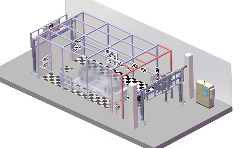
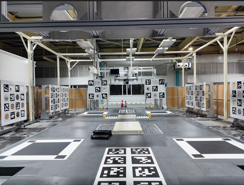
Advanced Driver Assistance Calibration System——ADAS-2000
Contact Us
Keywords


Telephone:
E-mail:
ZhenHua Packing Machinery
Online Message
WebsiteConstruction: China Cross-border Enterprise | SEO
在线客服添加返回顶部
右侧在线客服样式 1,2,3 1
图片alt标题设置: Iyasaka (Beijing) Automotive Technology Co., Ltd.
表单验证提示文本: Content cannot be empty!
循环体没有内容时: Sorry, no matching items were found.
CSS / JS 文件放置地